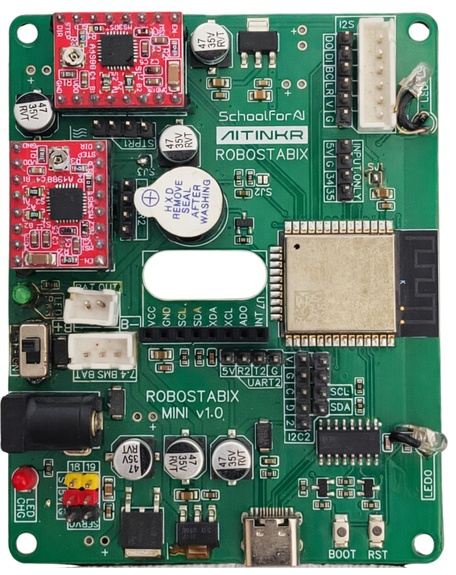
RobostaBIX Mini v1.0.
Stepper, Servo & IoT BoardA compact ESP32-based robotics control board with dual A4988 stepper driver sockets, dedicated 5 V servo rail, and onboard MPU6050 IMU. Designed for mobile robots, balance bots, CNC stages, and IoT-enabled automation projects.
Made in India · Tuned for robotics labs, makers, and competition teams.
About
RobostaBIX Mini v1.0
ESP32 stepper, servo, and IoT controller for compact robots
SKU
AT-RBX-MINI-10
Latest Release
Feb 2026
Edited
Feb 2026
The RobostaBIX Mini v1.0 is a compact ESP32-based robotics control board built for stepper motors, servo motors, sensors, and IoT-enabled robotic applications. With dual A4988 driver sockets, dedicated servo power, and an onboard MPU6050 IMU, it is ideal for mobile robots, balance bots, CNC mechanisms, and automation projects.
The power system is designed around Li-Ion/LiPo packs with onboard charging, a main 5 V regulator, and a separate 5 V rail for servos. This keeps the ESP32 and sensors stable even under high motor load. Clear LEDs for power and charging, along with labelled headers for battery and external supply, make it easy to troubleshoot and deploy in the field.
Rich connectivity options include UART2, dual I²C buses, and an I²S header, plus dedicated headers for analog-only and digital-only inputs. Combined with the MPU6050 IMU, this lets you build self-balancing platforms, sensor-rich rovers, and connected motion systems that stream telemetry or respond to cloud commands.
RobostaBIX Mini also includes boot and reset buttons, expansion headers with 5 V/GND/signal rails, and careful routing around the A4988 driver area for reliable high-current motor operation. It is a practical controller for learning motion control as well as for serious prototyping in labs and competition teams.
Tech Specs
Microcontroller
ESP32-WROOM module, dual-core 32-bit LX6, up to 240 MHz
Flash / SRAM
4 MB flash, 520 KB SRAM
Wireless
Wi-Fi 802.11 b/g/n, Bluetooth v4.2 BR/EDR + BLE
Logic Voltage
3.3 V core logic
Stepper Drivers
2× A4988 stepper driver sockets (STPR1, STPR2)
Motor Enable
GPIO 12 (PIN_ENABLE_MOTORS) – shared enable for both drivers
Motor 1 Control
DIR – GPIO 27, STEP – GPIO 14
Motor 2 Control
DIR – GPIO 32, STEP – GPIO 33
Servo Outputs
2× servo headers – SERVO1 (GPIO 19), SERVO2 (GPIO 18), 5 V
Onboard IMU
MPU6050 6-axis accelerometer + gyroscope (I2C on GPIO 21/22)
Primary I²C Bus
SDA – GPIO 21, SCL – GPIO 22
Secondary I²C2 Bus
GPIO 2 (general I²C2), SDA – GPIO 4, SCL – GPIO 5
UART
UART2 – RX2 (GPIO 16), TX2 (GPIO 17), 5 V tolerant header
I²S Audio Header
BCLK – GPIO 23, LRCLK – GPIO 25, DOUT – GPIO 26, DIN – GPIO 39 (input only)
Battery Input
JST connector for Li-Ion / LiPo (1S–2S) via BAT OUT, 7.4 V BMS BAT port
Charging Circuit
Onboard Li-Ion/LiPo charger with CHG status LED
Voltage Regulation
Main 5 V regulator plus dedicated 5 V servo rail for stable actuation
Indicators
LED PWR (power), LED CHG (charging)
Additional Inputs
GPIO 34 (IN34) and GPIO 35 (IN35) – analog/digital input only, up to 5 V
LED Outputs
GPIO 0 – LED0, GPIO 15 – LED12
Battery Voltage Sense
GPIO 36 (IN36_BATV) – optional battery voltage sensing via jumper
Onboard Buzzer
GPIO 13 – buzzer output
Learning Resources
Contact us
Get in Touch With Us
- Phone number
- 91 99492 96431
- hello@aitinkr.com
Business Hours :
Monday - Saturday: 9:00a.m to 8:00p.m
Sunday: With Appointment Only
Send a Message
Write to us. We would catch up with you as soon as we receive your message